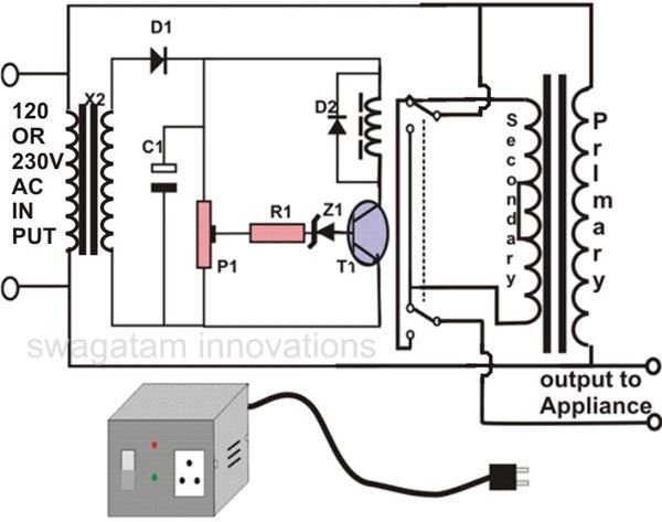
Manual Stepped Voltage Stabilizer Circuit Diagram

Description Here Is The Circuit Diagram Of A Powerful 12v Regulator That Can Deliver Up To 15 A Of Cur Voltage Regulator Circuit Diagram Electronic Schematics

100 Power Supply Circuit Diagram With Pcb Eleccircuit Com Power Supply Circuit Simple Electronic Circuits Electronic Circuit Projects

Automatic Voltage Stabilizer Circuit Diagram Circuit Diagram Circuit Pic Microcontroller

Usb 5v To 1 5v 3v Step Down Converter Circuit Eleccircuit Com Circuit Usb Battery Charger Circuit
How To Make An Automatic Voltage Stabilizer Circuit Construction Explained Bright Hub Engineering

Automatic Voltage Stabilizer Circuit Diagram Circuit Diagram Circuit Diagram

The specialty of this ic is low drop out voltage because of the use of mosfet as internal series pass element.
Manual stepped voltage stabilizer circuit diagram.

Lm350 Voltage Regulator Circuit Diagram Voltage Regulator Electronics Projects Regulators

Solid State Scr Triac Controlled Automatic Voltage Stabilizer Circuit Projects Circuit Electronics Circuit

Voltage Stabilizer Wiring Diagram Automotive Electrical Diagram Bp Oil

How To Use Hall Effect Sensor With Arduino Working Hook Up Guide And Relay Control In 2020 Hall Effect Arduino Sensor
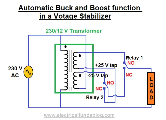
What Is Voltage Stabilizer Why We Need It How It Works Types And Applications

Virtual Ground Regulated And Rail Splitter Circuits Headphone Reviews And Discussion Head Fi Org Circuit Voltage Regulator Current Source

Diy Automatic Solar Charge Controller Solar Circuit Diagram Solar Panels

New Wiring Diagram For Ac Compressor Air Compressor Pressure Switch Exhaust Fan Industrial Refrigerator Compressor

Lcd Tv Repair Guide Lcd Television Lcd Tv Electronics Basics

Lm2596 Pinout Voltage Regulator Electronics Basics Electronic Schematics

1000 Volt Dc To Dc Regulator Circuit Elektronika Transformatory Tokio

How Do You Build A Simple Circuit To Control A Servo Simple Circuit Electronics Circuit Circuit

Buck Converter Working Step 2 Converter Voltage Regulator Inductors

Stepper Motor Driver Using Pic18f4550 Microcontroller Voltage Regulator Microcontrollers Stepper Motor

Simple 12v 1 Amp Smps With Pcb And Transformer Winding Details Carregador Eletronicos Fontes

Schematic Diagram Electronics Basics Circuit Circuit Board

Preher Tech Lcd Tv Repair Guide Lcd Television Lcd Tv Repair Guide

Arduino Interface Mc3479 Stepper Motor Controller Arduino Stepper Motor Steppers
Search Q 12v 12 Volt Regulator Circuit Tbm Isch

Start Run Capacitor Wiring Diagram And Kwikpik Me Motor Circuit 1440 Best Of Starting Electronic Circuit Projects Circuit Projects Water Pump Motor

Lm2576 Buck Converter Pinout Specs Equivalent Circuit Datasheet In 2020 Electronics Basics Electronic Schematics Electronic Circuit Projects

Control Stepping Motor Via Usb Interface Electronic Schematics Electronics Basics Pic Microcontroller

Pin On Energia

Snubber Circuit Design Analysis Electronicsbeliever In 2020 Circuit Design Circuit Analysis

Digital Temperature Sensor Circuit Circuit Diagram Digital Thermometer Digital Circuit

Circuit Diagram Of Stepper Motor Diy Electronics Electronic Schematics Electronics Circuit

I Pinimg Com 474x 4f 2e 05 4f2e05d03cc9b8b68d08

Over Under Voltage Protection Circuit Eleccircuit Com Circuit Circuit Projects Electronics Circuit

Bipolar Stepper Motor Driver Circuit Design Stepper Motor Circuit Design Steppers

Open Full Image In A New Tab High Voltage Electronic Circuit Projects Circuit

Automobile White Led Light White Led Lights Led Lights Led

Electrical Page Dc Motor Control Circuit Diagram Circuit Diagram Electrical Circuit Diagram Electronic Circuit Design

Lm317 Lm338 Lm350 Voltage Regulator Calculator And Circuits Voltage Regulator Regulators Circuit
101 200 Transistor Circuits Electronic Schematics Electronic Circuit Projects Electronics Circuit

Easy Draw Smartphone Schematic Diagrams Zxw Alternative 1 Year Active Easy Drawings Diagram Best Server

Electrical Blog Ac Motor Control Circuit Electrical Circuit Diagram Electronic Engineering Electrical Wiring Diagram

Simple 12v 1 Amp Smps With Pcb And Transformer Winding Details Carregador Eletronicos Fontes

Manual Eprom Programmer Circuit Diagram Electronics Projects Electronics For You

Diagrama De Cableado Cableado De Un Generador Portatil A Casa Manual Del Diagrama De Cableado Del Transfer Switch Portable Generator Generator Transfer Switch

High Voltage Inverter Circuit Diagram High Voltage Circuit Diagram Electronics Circuit
Http Www Ijlret Com Papers Vol 3 Issue 6 1 B2017170 Pdf

Pin On Elektronika

Simple 12v To 9 7 5 Or 6v Dc Converter Schematic This Dc To Dc Converter Circuit Enables Electronic Circuit Projects Power Supply Circuit Electronics Circuit
Https Encrypted Tbn0 Gstatic Com Images Q Tbn 3aand9gcqmo5aklb7mjktb3nfavturlawjgqgq8igljgpv2qjsrvdzevzz Usqp Cau
Source : pinterest.com
